History
The Mantons:
The best history of the Mantons is found in The Mantons: Gunmakers by W. Keith Neil and D.H.L. Back. This book, published in 1966, is the source for the historical information presented here. The Manton brothers, John (1752-1834) and Joseph (1766-1835) were regarded in their time as England's finest gunsmiths and almost single-handedly established London as the center for fine gunmaking. Joseph worked with his brother for a short period before they split to form their rival gunsmithing firms, and after that, their rivalry was often rancorous, even to the point of a lawsuit being filed by Joseph against his older brother for patent violation. Of the two, Joseph was more widely inventive and was best known for his double-barrel fowlers and early percussion locks, while John was most famous for his pistols and single barrel guns. Perhaps because of John's innate conservatism, he produced flintlocks until 1825, when he reluctantly switched to percussion. It was because of his pursuit of excellence in flintlock arms that we owe his last and most popular invention, the V-pan lock, patented in 1815, a time when percussion arms of various types were coming into use. This may have been the reason his business picked up to about 300 guns/year for the next seven years; thereafter it dropped to about 100/year until his death. The firm continued on as 'Manton and Hudson'.
The V-Pan Patent Lock:
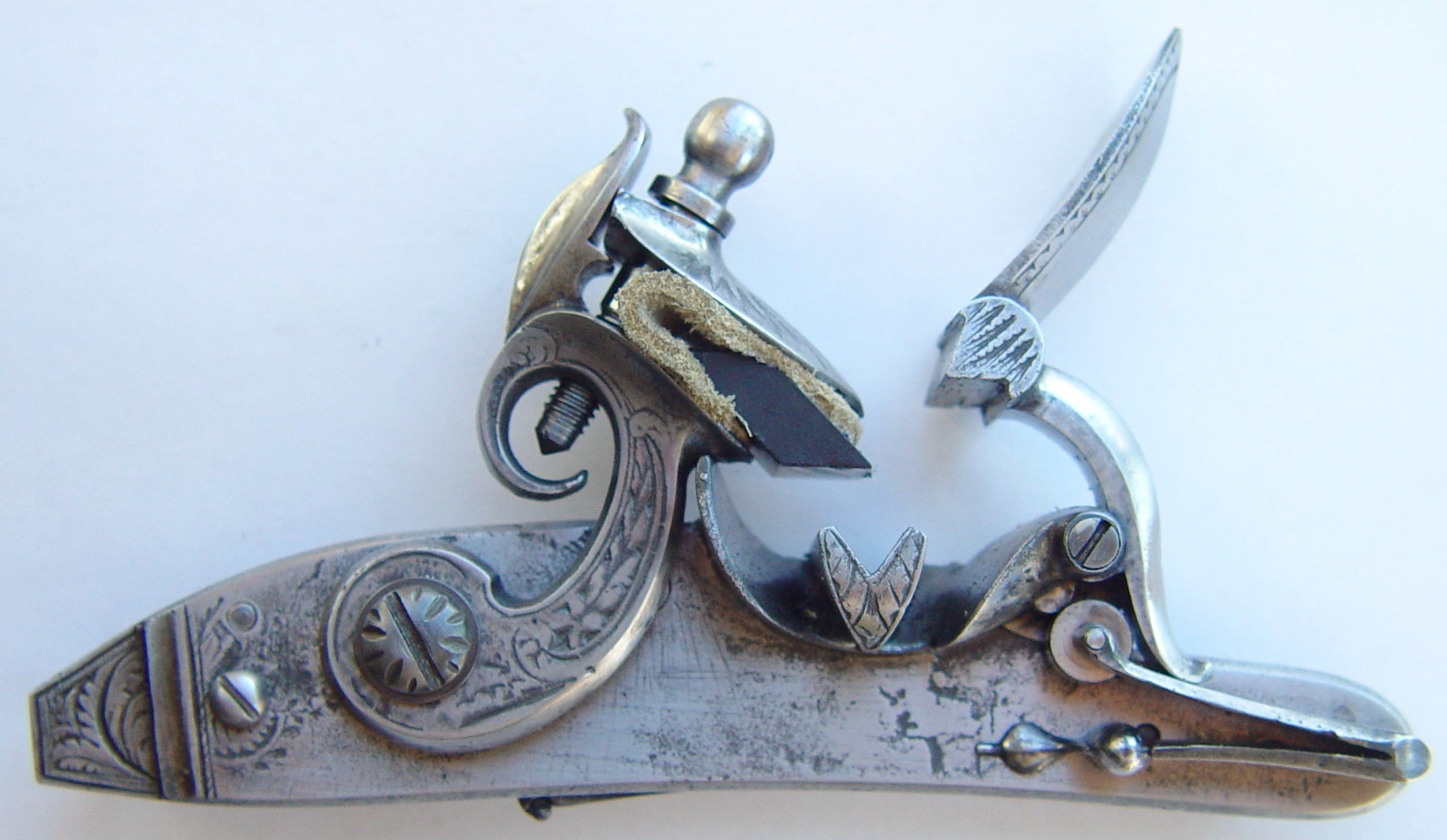
Manton locks had always been known for their speed. The Mantons were the first gunmakers to utilize strong springs with long tumbler arms and short-throw cocks, which provided tremendous hammer speed. This arrangement tended to eat flints, but since their early products were largely dueling pistols, a single, quick shot was all that was required. This practice was quickly adopted by other gunmakers, so the Mantons tried any number of improvements to gain a competitive advantage. In 1815, John Manton developed and patented the last of his flintlock improvements, the divided V-pan lock. In this lock, a semi-circular pan was mated to a V-shaped pan cover, with a platinum bar running lengthwise in the pan, just touching the ridge of the 'V', which divided the pan into two sections. When the lock was fired, the frizzen lifted and exposed two partially opposed flat powder surfaces, which were ideal for catching the sparks and then channeling the flame to the touch hole. The bar along the pan was to prevent powder in an incompletely filled pan from shifting while the gun was carried.
Of interest to modern muzzleloader shooters is that this, and most of the Manton brothers
locks were of the 'self-priming' variety. A hole in the side of the frizzen cover
communicated to the pan so the powder from the main charge would fill the pan when the gun was
loaded. To prevent the 'fuse effect' from slowing ignition, a 'vent wiper' was
used. This small appendage to the frizzen cover literally pulled powder away from the touch
hole as the cover lifted, allowing the incandescence from the burning pan powder to directly
ignite the main charge. This says several things about 18th century shooters:
a) They were interested in convenience.
b) They did not have our safety concerns.
c) They did not have a separate grade of priming powder.
d) They used larger touch holes (which really helps lock speed), and may have used
finer-grained powder.
So what did they cost?
[Note: This information has been updated from the original posting, where there was, to say the least, a substantial calculation error. We regret the confusion.] The Manton brothers' guns were expensive, to say the least. It is difficult to directly compare what something cost 180 years ago to its equivalent price today, but some approximations can be made. In 1815, the time of the invention of this lock, a Manton single-barreled fowler sold for 25 guineas, and a "London Best" double sold for 55 guineas - accessories and case were extra. A gold guinea contained 7.98 grams of 22/24 carat gold, or 7.315 grams of fine gold. At todays price of $1,300/ounce, a guinea is therefore worth $305 as gold bullion, so in those terms, a single cost about $7,600 and a double about $16,800 - about what a really high grade modern shotgun goes for. However, this is deceiving, because the price of gold relative to what it will buy is not necessarily a good measure of actual wages and living expenses. Another measure is to look at "purchasing power parity" (PPP), a measure of how far money actually goes in a particular time or society. A PPP table shows the 1815 guinea to be worth about £8.03 in 1974 terms, and using these inflation tables and the current dollar conversion rate, we come to a figure of about $90.13/guinea in 2001. This puts the relative price of the nice double shotgun at nearly $5,000. A good salary for a cleric or skilled laborer was reported to be a guinea per month, so such guns were clearly for the landed nobility. The price for a military musket or a common gun was generally less than a guinea.
So where can I get one?
As an avid flintlock shooter, I have always wanted to own a rifle or single barrel fowler with a Manton V-Pan lock, but I have not yet found one. There are, however, rough castings available for one at The Rifle Shoppe, so I ordered the set (#531). For the reader who has not seen a lock "kit" in this form, it arrives as a plastic bag containing a pile of metal pieces, with no pictures, instructions or anything. There are helpful instructions regarding metal heat treatment in the TRS catalog, but generally, the company assumes you know what you are doing when you order the castings. Assembling such a fine lock from a pile of rough parts is a daunting task, especially since I have never done one like this before, so I thought I would document the project - and any of my mistakes - so that others might learn from them.
The Original Lock
 This is the original lock, now in a private collection, from which the
castings were made. Note that the lock is marked "Baucheron Pirmet A Paris". Pirmet
was a student of Boutet, perhaps the most famous French gun maker. An interesting question is
whether this lock was made by Pirmet based on the Manton lock, or if it was a lock he bought
from Manton and then added his name to it. My guess is that it was the latter, because the lock
decorations are exactly those used by Manton. In either case, it is idential to known examples
by Manton himself.
This is the original lock, now in a private collection, from which the
castings were made. Note that the lock is marked "Baucheron Pirmet A Paris". Pirmet
was a student of Boutet, perhaps the most famous French gun maker. An interesting question is
whether this lock was made by Pirmet based on the Manton lock, or if it was a lock he bought
from Manton and then added his name to it. My guess is that it was the latter, because the lock
decorations are exactly those used by Manton. In either case, it is idential to known examples
by Manton himself.
The Castings
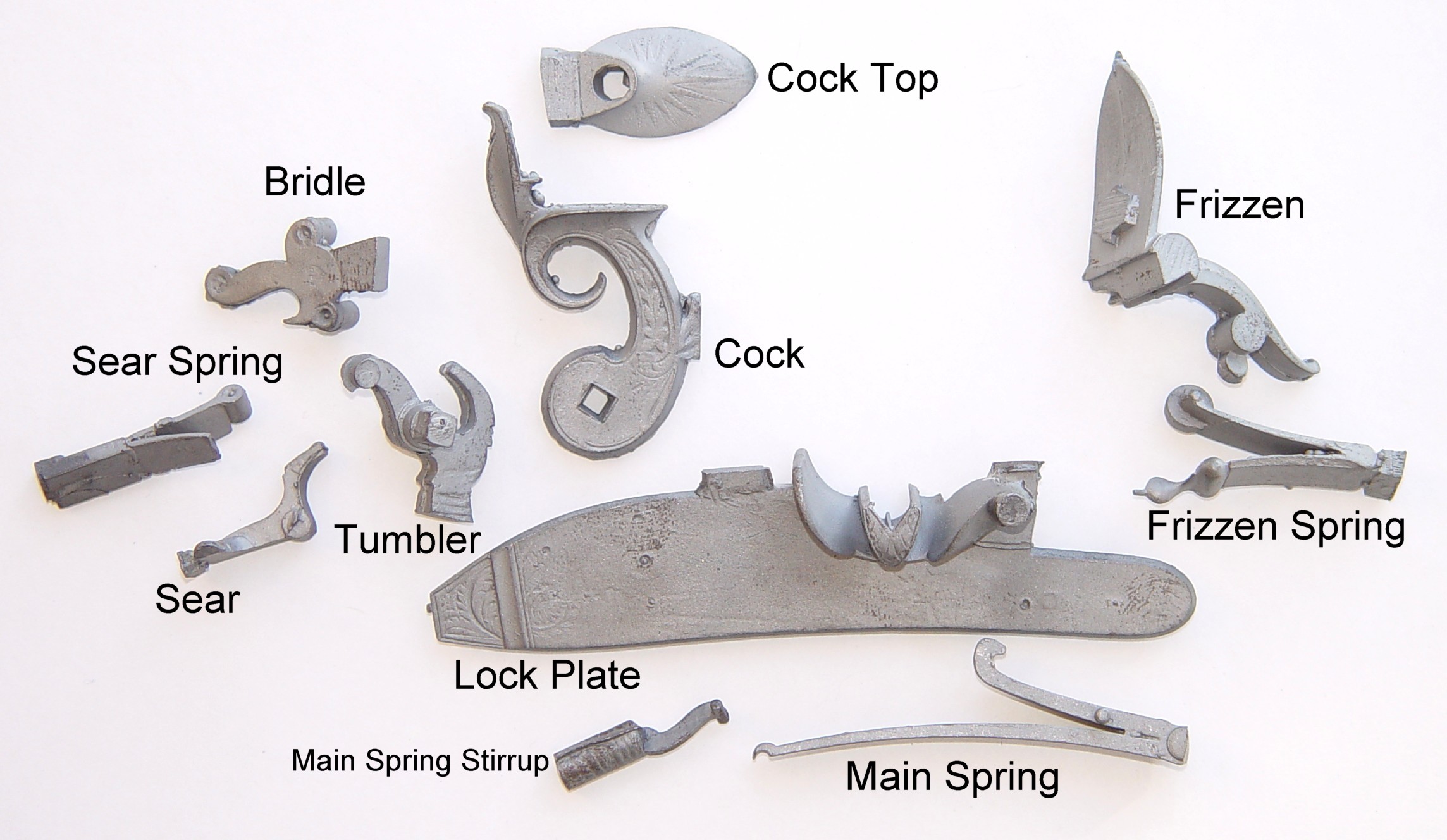 This is how the
castings look out of the bag. As you can see (especially if you click to get a large image),
rough castings are - well - rough! The edges are somewhat irregular, the casting sprues
are still in place, and there are only small dimples which suggest the proper placement of the
required drill holes. No screws are provided (they are available separately, but I prefer to
make my own). It is important to keep in mind that the castings are from original locks and, in
addition to exactly copying whatever wear and corrosion was present, the locks could not be
completely dissasembled in order to make the castings. Thus, you see the frizzen spring roller
in the picture is not really a roller but actually a solid part of the casting; I will describe
how to handle this later. In addition to errors encountered in making the master molds, errors
accumulate in wax injection, investing, etc, so the final pieces are guaranteed not to fit well
without a good deal of thoughtful work. Although assembling a functioning lock from rough
castings can theoretically be done with only hand tools, I would not attempt it without at
least a lathe and drill press, and preferably a mill as well. There are probably any number of
ways to start the project, but I shall begin with the lockplate.
This is how the
castings look out of the bag. As you can see (especially if you click to get a large image),
rough castings are - well - rough! The edges are somewhat irregular, the casting sprues
are still in place, and there are only small dimples which suggest the proper placement of the
required drill holes. No screws are provided (they are available separately, but I prefer to
make my own). It is important to keep in mind that the castings are from original locks and, in
addition to exactly copying whatever wear and corrosion was present, the locks could not be
completely dissasembled in order to make the castings. Thus, you see the frizzen spring roller
in the picture is not really a roller but actually a solid part of the casting; I will describe
how to handle this later. In addition to errors encountered in making the master molds, errors
accumulate in wax injection, investing, etc, so the final pieces are guaranteed not to fit well
without a good deal of thoughtful work. Although assembling a functioning lock from rough
castings can theoretically be done with only hand tools, I would not attempt it without at
least a lathe and drill press, and preferably a mill as well. There are probably any number of
ways to start the project, but I shall begin with the lockplate.
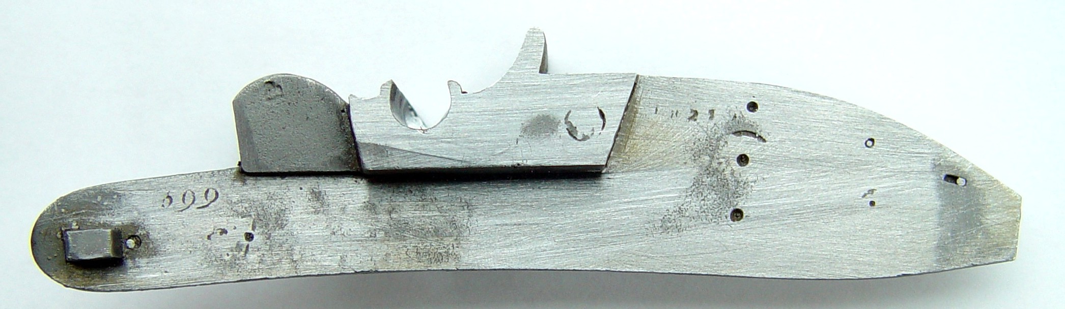
The Lockplate
The lock plate is a long, thin piece of metal, and during the casting process it is subject to uneven cooling - putting it charitably, it is 'as crooked as a dawgs hind laig'. The lock should be perfectly flat across the back (except for the lumpy parts that are supposed to be there...), and to get it that way, there are two basic techniques.
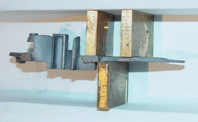 My
preferred method, shown here, is to use a sturdy metal vise with brass blocks and warp it back
into shape. This should be done in slow stages, keeping note of how far the vise is closed each
time, and using a straight edge held against the back of the plate, with a good light behind
it, to measure your progress. A vertical bench press would be even better if one is available.
Another method is to hold a straight part of the lockplate in the vise (using brass blocks) and
use a copper hammer to 'whang' the part into shape by striking the bent section,
causing it to slightly bend with each blow. If done carefully, this also works well. The lock
plates from TRS are 4140 cast steel, and from the mold are fairly malleable. When heat treated
(more on this later) they become incredibly tough, so all bending, drilling, filing or other
manipulation should be done in their untreated state.
My
preferred method, shown here, is to use a sturdy metal vise with brass blocks and warp it back
into shape. This should be done in slow stages, keeping note of how far the vise is closed each
time, and using a straight edge held against the back of the plate, with a good light behind
it, to measure your progress. A vertical bench press would be even better if one is available.
Another method is to hold a straight part of the lockplate in the vise (using brass blocks) and
use a copper hammer to 'whang' the part into shape by striking the bent section,
causing it to slightly bend with each blow. If done carefully, this also works well. The lock
plates from TRS are 4140 cast steel, and from the mold are fairly malleable. When heat treated
(more on this later) they become incredibly tough, so all bending, drilling, filing or other
manipulation should be done in their untreated state.
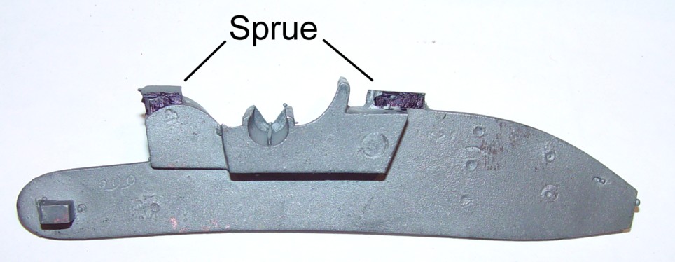 Next (or,
it could be done before), I remove the sprue and clean up any flashings. As you can see from
the photos, the sprue-casting line can be very clear, or it may be indistinct. In some cases, a
portion of the part may be inside the sprue, so take some care to identify exactly what to
remove. In the photo, the sprue to the left meets the lock plate in a compound curve which
matches that of the frizzen. In cases like this, you may want to leave a little sprue in place
and wait until final assembly to even out the final contours. Also, don't just take the
sprue off all parts; it is useful in some cases, particularly with springs, to use it as a
'handle' when filing, and it is then removed only in the last finishing
step.
Next (or,
it could be done before), I remove the sprue and clean up any flashings. As you can see from
the photos, the sprue-casting line can be very clear, or it may be indistinct. In some cases, a
portion of the part may be inside the sprue, so take some care to identify exactly what to
remove. In the photo, the sprue to the left meets the lock plate in a compound curve which
matches that of the frizzen. In cases like this, you may want to leave a little sprue in place
and wait until final assembly to even out the final contours. Also, don't just take the
sprue off all parts; it is useful in some cases, particularly with springs, to use it as a
'handle' when filing, and it is then removed only in the last finishing
step.
 Use either a
large diamond file or 2" X 6" flat diamond honing block for cutting flat surfaces.
These are available inexpensively from sources such as Harbor Freight, and they are ideal for this type of work.
You should also get a set of diamond grinding wheels for flashing removal and metal removal in
small corners; Lasco Diamond Products is a
good source for these as well as rubberized abrasive wheels for finishing. I generally keep the
file or block supported and move the piece against it; this gives me a better feel for the
piece's alignment and how well it is cutting; use just water as a lubricant, but remember
that any steel surface cut by a diamond will rust almost instantly, so put on a thin coat of
oil immediately after cutting is finished. This is how the flattened and filed lockplate should
look; the back should not be completely filed and polished at this time, as more work will be
done later.
Use either a
large diamond file or 2" X 6" flat diamond honing block for cutting flat surfaces.
These are available inexpensively from sources such as Harbor Freight, and they are ideal for this type of work.
You should also get a set of diamond grinding wheels for flashing removal and metal removal in
small corners; Lasco Diamond Products is a
good source for these as well as rubberized abrasive wheels for finishing. I generally keep the
file or block supported and move the piece against it; this gives me a better feel for the
piece's alignment and how well it is cutting; use just water as a lubricant, but remember
that any steel surface cut by a diamond will rust almost instantly, so put on a thin coat of
oil immediately after cutting is finished. This is how the flattened and filed lockplate should
look; the back should not be completely filed and polished at this time, as more work will be
done later.
Oops - The first error - or maybe not...
If you look closely at the rough casting (click on the picture for a larger version), you can see a ridge of metal at the bottom of the pan. This is the pan divider which is the subject of Manton's 1815 patent, and I neatly ground it away! I cleaned up the casting before I got the reference book, so I had assumed the ridge was just another sprue or air vent. In defense, I'm not sure what I would have done in any case. The original ridge was platinum, and leaving the steel cast-in ridge would have made the pan almost impossible to finish; the insides were extremely rough and needed a good deal of grinding. If I want to be perfectly period-correct, I can install a platinum bar with platinum pan lining, but its absence will not affect the function of the lock as I will use it, since I will be externally priming the lock.
Fitting The Frizzen
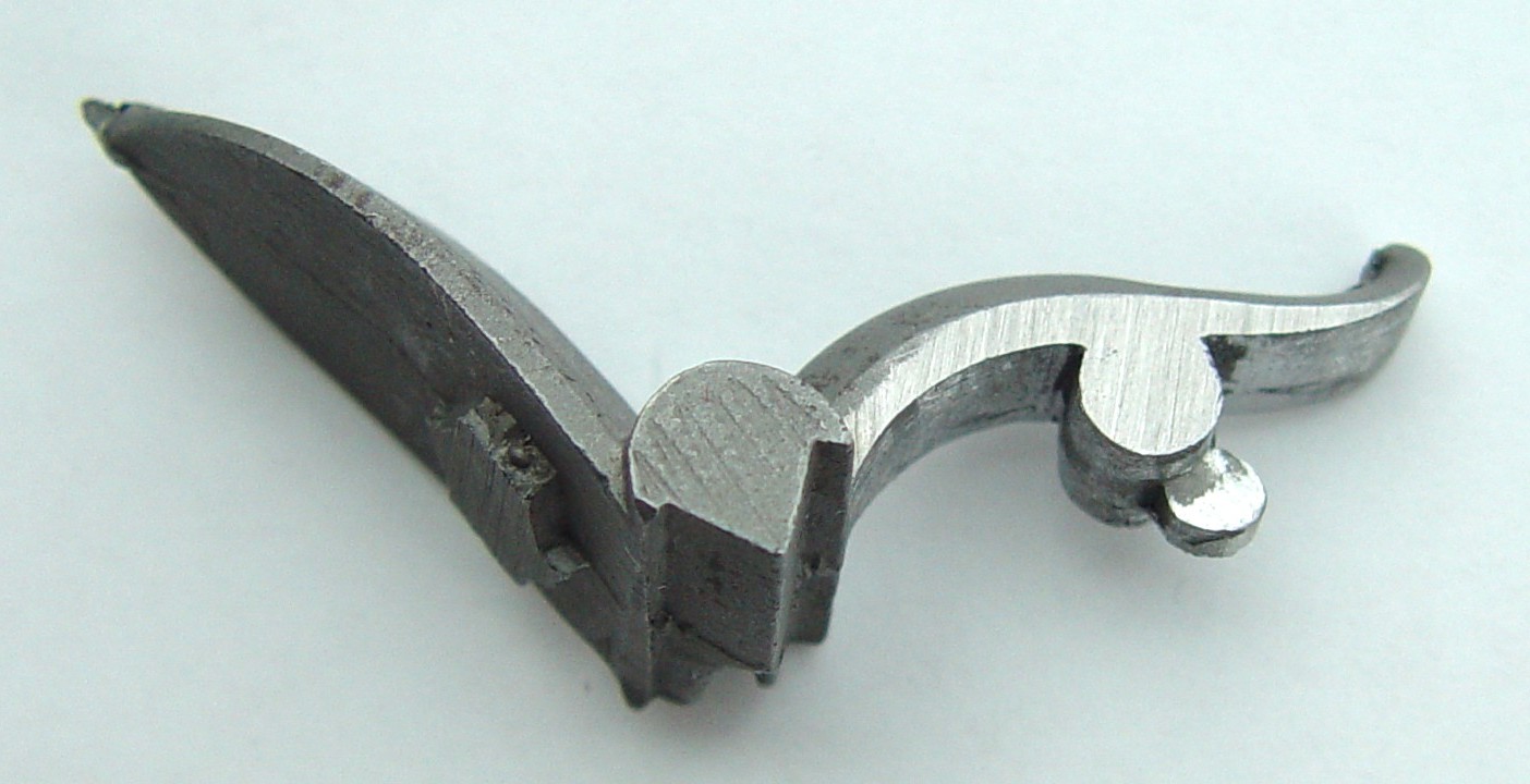 Fitting the frizzen and frizzen spring are
one of the trickier aspects of this lock, so these will be tackled next - if things are going
to be messed up, I would rather it happen now! Begin by honing the sides and pivot just enough
to make sure they are clean and parallel. Clean up any flashing on the underside of the frizzen
and make sure the part which mates with the pan is a clean, straight line. The little metal
disk at the bottom of the frizzen pivot is what bears against the frizzen spring roller; it
should be round, with smooth, parallel sides. Do not bother to polish the part or remove file
marks at this time.
Fitting the frizzen and frizzen spring are
one of the trickier aspects of this lock, so these will be tackled next - if things are going
to be messed up, I would rather it happen now! Begin by honing the sides and pivot just enough
to make sure they are clean and parallel. Clean up any flashing on the underside of the frizzen
and make sure the part which mates with the pan is a clean, straight line. The little metal
disk at the bottom of the frizzen pivot is what bears against the frizzen spring roller; it
should be round, with smooth, parallel sides. Do not bother to polish the part or remove file
marks at this time.
 The frizzen pivot
needs to be mated to the frizzen pivot socket on the lockplate and the frizzen to the pan. It
is very difficult to fit a file or a small grinder into the socket recesses, so I do most of
the metal removal with a graver, shaving off tiny pieces at a time until a fit is achieved. If
this sounds tedious, it is - fitting the frizzen took me the better part of a day. At this
point, the only concern should be removing enough metal from the frizzen pivot and the socket
to allow the frizzen to mate with the pan; you will also need to flatten and remove some metal
from the sides of the pan as well. All this needs to be done very slowly and carefully, testing
the fit after every operation. Aside from removing metal, the frizzen may need to be twisted
slightly to make the frizzen and pan align throughout their widths; use machinists blue
(similar to inletting black for wood) to see which parts mate properly. The goal should be to
have the frizzen pivot just fit in the socket, with the edges of the pan tight against the
frizzen. It is better to get a good fit now than try to repair a bad one later. Remember the
most important fit is that of the pan edges; the frizzen pivot screw will take up some slack on
that joint, so if pressure on the top of the frizzen makes it perfectly mate with the pan, you
are done.
The frizzen pivot
needs to be mated to the frizzen pivot socket on the lockplate and the frizzen to the pan. It
is very difficult to fit a file or a small grinder into the socket recesses, so I do most of
the metal removal with a graver, shaving off tiny pieces at a time until a fit is achieved. If
this sounds tedious, it is - fitting the frizzen took me the better part of a day. At this
point, the only concern should be removing enough metal from the frizzen pivot and the socket
to allow the frizzen to mate with the pan; you will also need to flatten and remove some metal
from the sides of the pan as well. All this needs to be done very slowly and carefully, testing
the fit after every operation. Aside from removing metal, the frizzen may need to be twisted
slightly to make the frizzen and pan align throughout their widths; use machinists blue
(similar to inletting black for wood) to see which parts mate properly. The goal should be to
have the frizzen pivot just fit in the socket, with the edges of the pan tight against the
frizzen. It is better to get a good fit now than try to repair a bad one later. Remember the
most important fit is that of the pan edges; the frizzen pivot screw will take up some slack on
that joint, so if pressure on the top of the frizzen makes it perfectly mate with the pan, you
are done.
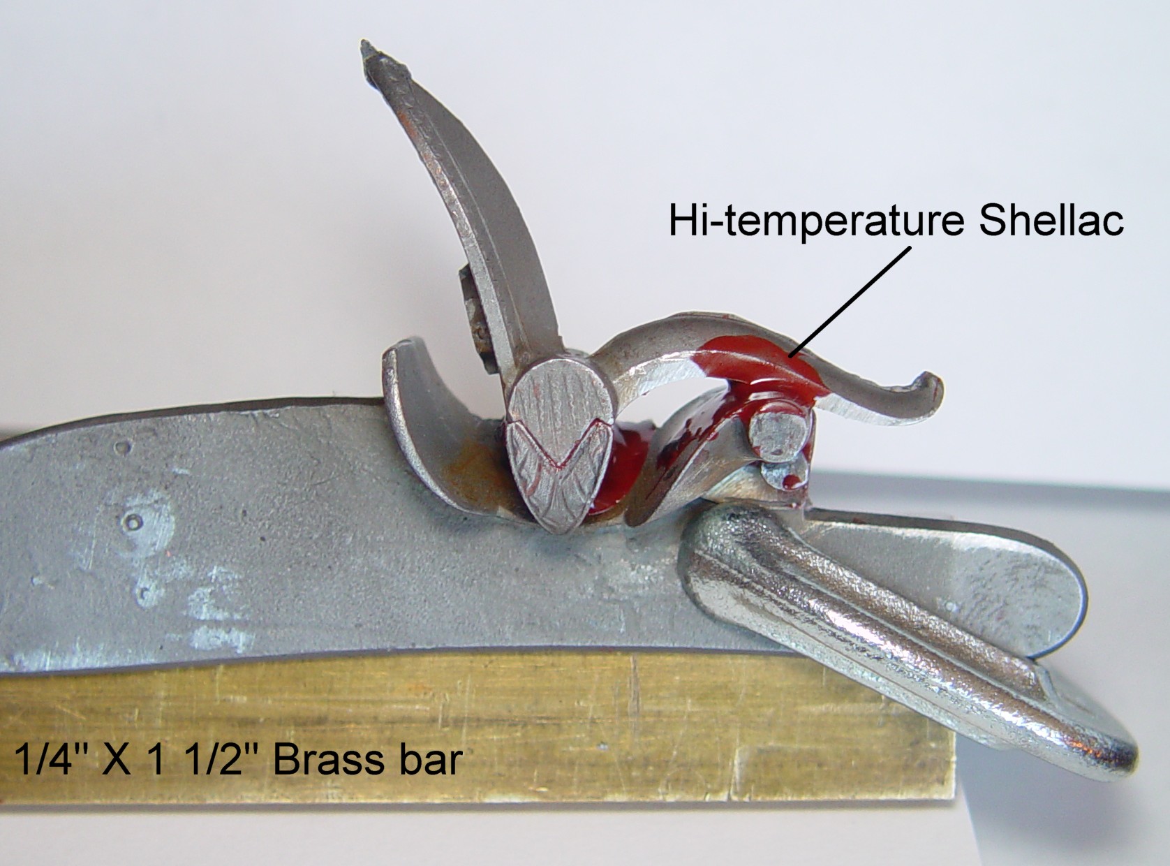 The next
step, drilling the frizzen pivot hole, is critical and will ruin the entire piece if not done
properly. It is imperative the frizzen and lockplate remain perfectly mated during the drilling
operation! Clamping the pieces together is inadequate, particularly in a lock with this
complicated a geometry. Some builders like to solder the pieces together, but solder is
difficult to remove and any remaining will spoil the finish. I prefer to use Raytech Diamond
Dop Wax, used by diamond cutters. This high-temperature shellac-based material is available in
stick form from suppliers such as ColorWright; I have
tried other materials such as hot-melt glue, but they don't work nearly as well as shellac.
Shellac hardens to a true solid, but the glues just become very stiff, and if you get the work
piece warm, they will shift. Here, you can see the shellac melted in the pan and frizzen pivot,
which locks the parts together as tightly as solder. The lockplate is then clamped to a brass
bar, which in turn will be clamped in a vise for drilling the hole.
The next
step, drilling the frizzen pivot hole, is critical and will ruin the entire piece if not done
properly. It is imperative the frizzen and lockplate remain perfectly mated during the drilling
operation! Clamping the pieces together is inadequate, particularly in a lock with this
complicated a geometry. Some builders like to solder the pieces together, but solder is
difficult to remove and any remaining will spoil the finish. I prefer to use Raytech Diamond
Dop Wax, used by diamond cutters. This high-temperature shellac-based material is available in
stick form from suppliers such as ColorWright; I have
tried other materials such as hot-melt glue, but they don't work nearly as well as shellac.
Shellac hardens to a true solid, but the glues just become very stiff, and if you get the work
piece warm, they will shift. Here, you can see the shellac melted in the pan and frizzen pivot,
which locks the parts together as tightly as solder. The lockplate is then clamped to a brass
bar, which in turn will be clamped in a vise for drilling the hole.
Mounting the brass bar in the vise as shown ensures the hole will be drilled perfectly perpendicular with the back of the lockplate. Center the hole exactly in the middle of the outer boss and start the hole with a center-drill. Standard high-speed steel drills can be used, but my preference is to use split-tip cobalt drills. In any case, the drill should turn at a very low RPM, and a good grade cutting oil should be used. It is important to remember that the 4140 steel, although annealed, can quickly work-harden, making it almost impossible to drill, so keep a steady pressure on the drill so it cuts rather than smooths, and clear chips frequently.
 It is almost
impossible to get a drill bit to produce the correct size hole when directly drilled, so the
first pass through-drilled the plate and frizzen using a #41 drill. The second pass with a #38
drill opened the hole to exactly 0.101" for the shaft. The piece was then heated enough to
remove the frizzen without affecting the alignment of the lockplate in the drill press (another
advantage of using the shellac). The outer part of the lockplate was then drilled to
0.111" (#34 drill) for tapping to 6-32. A #24 drill (0.152") was fitted and drilled
down 0.150" to accommodate the head of the screw. A 6-32 tap was held in the drill head
and turned by hand to form the threads. After the hole is drilled and tapped, the parts are
warmed and the bulk of the shellac is wiped off. Dunking the parts into a cup containing
alcohol will soften and remove any that remains.
It is almost
impossible to get a drill bit to produce the correct size hole when directly drilled, so the
first pass through-drilled the plate and frizzen using a #41 drill. The second pass with a #38
drill opened the hole to exactly 0.101" for the shaft. The piece was then heated enough to
remove the frizzen without affecting the alignment of the lockplate in the drill press (another
advantage of using the shellac). The outer part of the lockplate was then drilled to
0.111" (#34 drill) for tapping to 6-32. A #24 drill (0.152") was fitted and drilled
down 0.150" to accommodate the head of the screw. A 6-32 tap was held in the drill head
and turned by hand to form the threads. After the hole is drilled and tapped, the parts are
warmed and the bulk of the shellac is wiped off. Dunking the parts into a cup containing
alcohol will soften and remove any that remains.
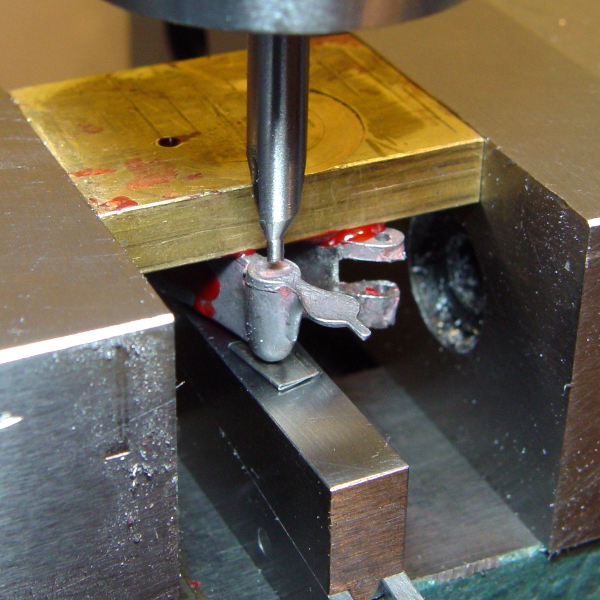
The next step is to perform whatever adjustments are required so the frizzen can open fully and completely. This will entail more filing and/or graving, using the machinists blue to find high spots. Use the shank of the #34 drill as a temporary axle for this fitting process; a permanent screw axle will be turned from 1/4" 4140 rod stock.
 One
characteristic of these locks which we don't encourage today is that they were
self-priming. The powder channel in the frizzen was aligned with the touch hole so the pan was
filled along with the main load. In this casting, a tiny lower portion of the 'V' is
missing. There should have been an actual hole in the face of the 'V' where the powder
channel exited. The part of the 'V' below the hole then acted as a vent wiper; when the
frizzen was flipped up after being struck by the flint, powder was flicked away from the touch
hole, preventing fuseing. I restored the frizzen in a 'politically correct' manner; a
small, square channel was milled in the frizzen with the lower edges cut back so a wedge-shaped
piece of 4140 bar could be driven in tight. High-temperature silver solder then filled all the
gaps. This way, at least I get the benefit of a clear vent when the lock fires.
One
characteristic of these locks which we don't encourage today is that they were
self-priming. The powder channel in the frizzen was aligned with the touch hole so the pan was
filled along with the main load. In this casting, a tiny lower portion of the 'V' is
missing. There should have been an actual hole in the face of the 'V' where the powder
channel exited. The part of the 'V' below the hole then acted as a vent wiper; when the
frizzen was flipped up after being struck by the flint, powder was flicked away from the touch
hole, preventing fuseing. I restored the frizzen in a 'politically correct' manner; a
small, square channel was milled in the frizzen with the lower edges cut back so a wedge-shaped
piece of 4140 bar could be driven in tight. High-temperature silver solder then filled all the
gaps. This way, at least I get the benefit of a clear vent when the lock fires.
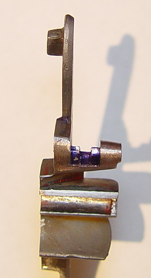
Fitting the Frizzen Spring and Roller
 The first
step is to flatten the back of the frizzen spring so the lower part can fit flat on the
lockplate while the top part clears the plate by about 0.10". In the picture note the use
of vice-grips to hold the sprue like a "handle" while working on it. After
flattening, the next step is to take the dimension of the roller (0.275" dia), because the
'solid' one will shortly be ground away.
The first
step is to flatten the back of the frizzen spring so the lower part can fit flat on the
lockplate while the top part clears the plate by about 0.10". In the picture note the use
of vice-grips to hold the sprue like a "handle" while working on it. After
flattening, the next step is to take the dimension of the roller (0.275" dia), because the
'solid' one will shortly be ground away.
 A
small hole is made in a piece of brass bar stock to accept the pin at the back of the spring,
and a 0.10" shim is placed under the roller to keep the proper alignment. Shellac is then
melted around the assembly and the bar is clamped in the vise. This is a simple way to hold the
complex assembly for drilling. The axle is through-drilled with a #56 drill and finished with a
#54 (0.055"). For the axle, either a piece of steel wire or a drill shank can be used.
A
small hole is made in a piece of brass bar stock to accept the pin at the back of the spring,
and a 0.10" shim is placed under the roller to keep the proper alignment. Shellac is then
melted around the assembly and the bar is clamped in the vise. This is a simple way to hold the
complex assembly for drilling. The axle is through-drilled with a #56 drill and finished with a
#54 (0.055"). For the axle, either a piece of steel wire or a drill shank can be used.
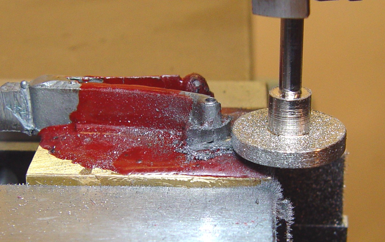 The
'roller' is ground out by using a diamond wheel. This produces less mechanical stress
than a slot-cutter; just make sure the piece is fed against the direction of the cut, and take
off only about 0.005" per pass. This operation generates a good deal of heat, so spritz
some water on it every pass or two, and let the piece and grinder cool if it becomes too warm
to the touch - you don't want the shellac to soften.
The
'roller' is ground out by using a diamond wheel. This produces less mechanical stress
than a slot-cutter; just make sure the piece is fed against the direction of the cut, and take
off only about 0.005" per pass. This operation generates a good deal of heat, so spritz
some water on it every pass or two, and let the piece and grinder cool if it becomes too warm
to the touch - you don't want the shellac to soften.
 A 4-40 hidden-head screw is used to attach the frizzen spring to the lockplate. Begin by
drilling the back of the frizzen spring by sticking it to the back of the brass block. Support
the back of the boss with a block and shim as shown, and drill a carefully centered 0.250"
deep hole with a #42 drill. Put a 4-40 tap into the drill head and hand-turn it to start the
threads, then remove the assembly from the vise and complete the threading by hand. Note that
4140 steel is 'sticky', and it is very easy to break a tap, especially in a blind hole.
You should rotate the tap only a small amount each time, then back off until the tap
doesn't feel like it is sticking.
A 4-40 hidden-head screw is used to attach the frizzen spring to the lockplate. Begin by
drilling the back of the frizzen spring by sticking it to the back of the brass block. Support
the back of the boss with a block and shim as shown, and drill a carefully centered 0.250"
deep hole with a #42 drill. Put a 4-40 tap into the drill head and hand-turn it to start the
threads, then remove the assembly from the vise and complete the threading by hand. Note that
4140 steel is 'sticky', and it is very easy to break a tap, especially in a blind hole.
You should rotate the tap only a small amount each time, then back off until the tap
doesn't feel like it is sticking.
Next, clean up and polish the frizzen spring prior to hardening. Make sure all material between the leaves is removed using a diamond disk and/or a slot-cutting file, and make especially sure there are no file marks running across the spring, since these are a focus for stresses and can lead to a spring fracture. The final polishing should be with at least a #400 grit emery paper. Finally, harden and temper the frizzen spring to 800 degrees; it is particularly delicate, so you may want to read this about tempering.
