Final Assembly and Finishing
Screwing around...
 The screws were turned from 4140 rod stock, water hardened,
tempered to a light blue and then repolished. The bridle and spring screws are standard size, but the cock cap
screw should have a shaft diameter fitted to the actual hole in the cock top. The frizzen and sear axle screws
should have very close tolerances to their respective holes. The screw set for this lock is seen to the
left.
The screws were turned from 4140 rod stock, water hardened,
tempered to a light blue and then repolished. The bridle and spring screws are standard size, but the cock cap
screw should have a shaft diameter fitted to the actual hole in the cock top. The frizzen and sear axle screws
should have very close tolerances to their respective holes. The screw set for this lock is seen to the
left.
Fitting the mainspring
The mainspring is cleaned up by filing and polishing. In my casting, there was a fair sized web where the leaves joined, and this was taken out with an abrasive disk, followed by using the edge of a thin, flat file. It is important to get the web out so as to minimize the chances of later breakage. Note that there are some casting marks on the tip of the spring which indicate about where the tip must be split to accept the spring stirrup. Don't go by these exactly (as I did to begin with... another error on my part). The slot in the mainspring tip must line up exactly with the slot in the tumbler arm, so assemble the tumbler and bridle and mark the mainspring tip accordingly, making sure to leave a little clearance between the mainspring tip and the lockplate.
 The hole for the mainspring pin is drilled into the
lockplate just forward of the frizzen spring hole and about 1/2 pin diameter up (mine got too far up for some
reason, but little harm was done). The hole for the pin should just touch the edge of the hole for the frizzen
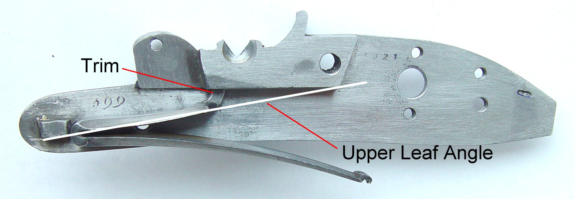
spring on the inside of the lockplate. The tab at the top of the mainspring should be carefully ground down until
a line drawn along the top leaf of the mainspring comes at or just above corner of the lockplate inner boss. This
will prevent the top leaf from potentially binding at full cock. [Note: I found that in this lock, the stirrup
was long enough to prevent this, but doing it this way made the spring assembly easier to compress and insert.].
The spring was then oil hardened and tempered to 750 degrees as shown here.
The hole for the mainspring pin is drilled into the
lockplate just forward of the frizzen spring hole and about 1/2 pin diameter up (mine got too far up for some
reason, but little harm was done). The hole for the pin should just touch the edge of the hole for the frizzen
spring on the inside of the lockplate. The tab at the top of the mainspring should be carefully ground down until
a line drawn along the top leaf of the mainspring comes at or just above corner of the lockplate inner boss. This
will prevent the top leaf from potentially binding at full cock. [Note: I found that in this lock, the stirrup
was long enough to prevent this, but doing it this way made the spring assembly easier to compress and insert.].
The spring was then oil hardened and tempered to 750 degrees as shown here.
The stirrup was cut from its sprue, taking care to remember the tip is actually imbedded half-way in the sprue. According to my drawings and photographs of locks of this type, the stirrup was attached to the tumbler arm with a screw. I thought this was overly difficult and excessive, so I simply countersunk the stirrup pin hole on the lockplate side of the tumbler arm a small amount. Then, I softened and peened the end of the 0.078" piano wire I used for the axle so that when mounted from the lock side, it fit flush with the surface of the tumbler arm but could not pull through. It was then cut to length. This allows easy removal of pin for any servicing, but the pin cannot back out of the hole since it is flush against the lockplate. This is also a more secure arrangement, since it can never back out, as can a screw.
Oops - re-tempering the springs
I did a trial assembly, and found all the springs to be too strong; the lock was difficult to cock, the frizzen was stiff, and the sear spring made the sear too hard to move. I put all the springs back into the heat bath and took them up to 800 degrees, which brought them to a more reasonable strength.
Finishing the lockplate
To harden or not to harden, that is the question... Hardening the lockplate, especially the tumbler axle hole, will help lock speed, but the lockplate being a long, thin piece of steel is easily warped during the hardening process; I compromised by air-hardening it. Although this will not harden it as well as oil or air, on a thin plate it will do almost as well for this purpose. Since even air hardening will make the lock very tough, the 10-32 mounting hole needed to be drilled and tapped first.
Note: These locks sit at a slight angle to the barrel, rather than straight up and down, which gives the guns a slimmer look and also swings the frizzen both up and out, keeping it from scraping the breech, even with a very tight fit. Therefore, the hole should be perpendicular to the inner surface of the boss and not the lockplate itself. Possible error? I drilled all the way through, as can be seen on some of Manton's locks, but in retrospect, there is enough thickness that a blind hole would have worked as well, and may look neater.
To harden the lockplate, I heated it evenly while it was resting on the pan side, keeping the plate vertical. After reaching hardening temperature (1350 degrees, or red-orange), a stream of cool air from a hair dryer was directed at the plate until it cooled below red, then it was slowly immersed edgewise into water. No tempering was required.
Final finishing, assembly and spark testing
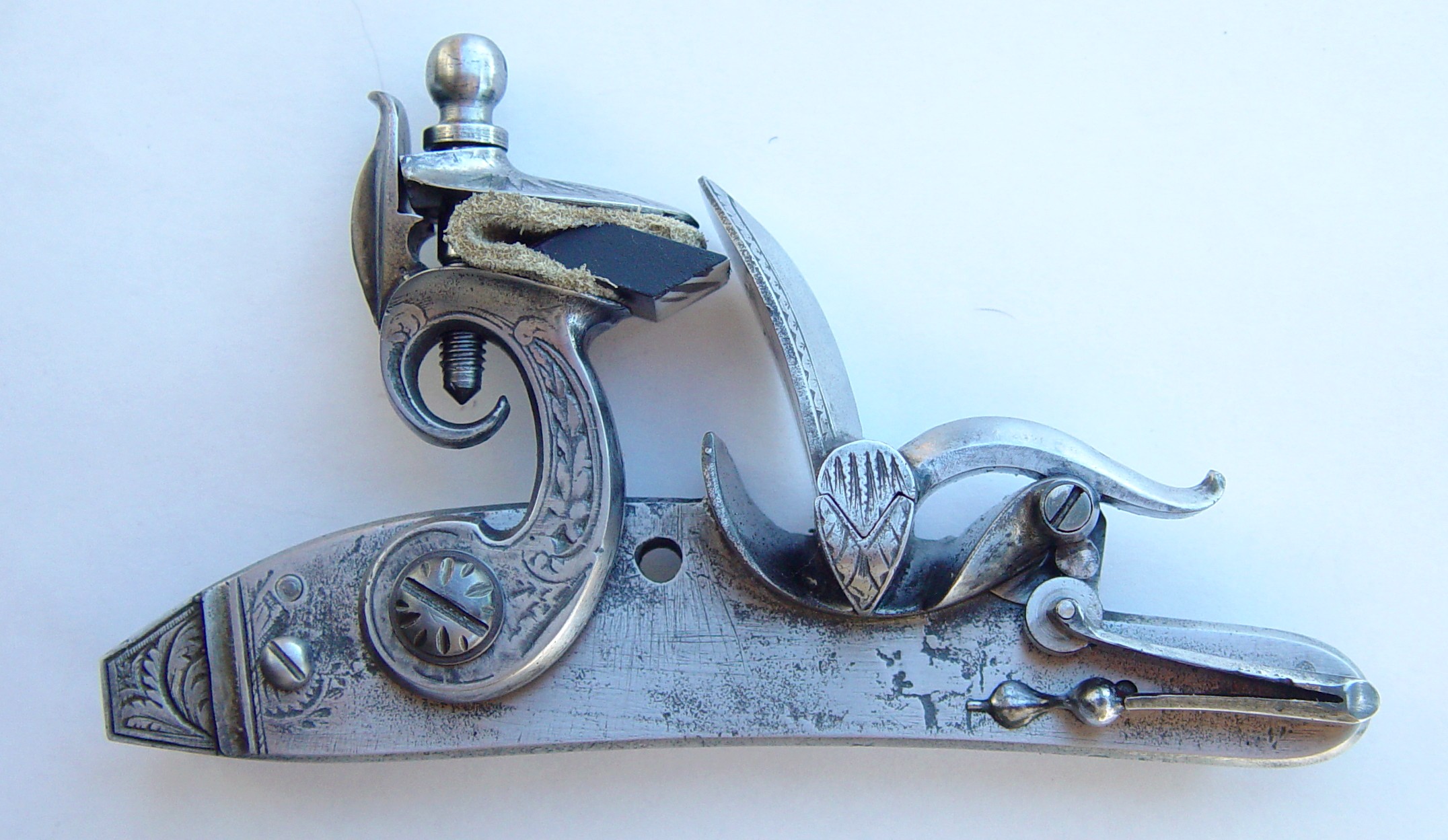
These castings have the engraving cast in place, so too heavy a finishing will obliterate them. However, there are also some corrosion areas (or casting errors) which can't be removed unless most of the 'engraving' is taken out too. Therefore, I elected to have a "cleaned up original" finish, with just a final wet sanding with 400 grit emery. I will be experimenting with artificial greying and might use that if it doesn't look too forced. All lock parts were wiped well with Eez_Ox, which gives excellent corrosion proofing, and the lock was assembled using molybdenum sulfide lubricant for all bearing surfaces, even including the sear.
 These locks have a very close geometry and require an
exactly-adjusted flint, inserted bevel-up. The path of the cock-fall makes the flint just graze the frizzen, and
if the flint is just a little too short, the cock cap will strike it instead. As I mentioned in the introduction,
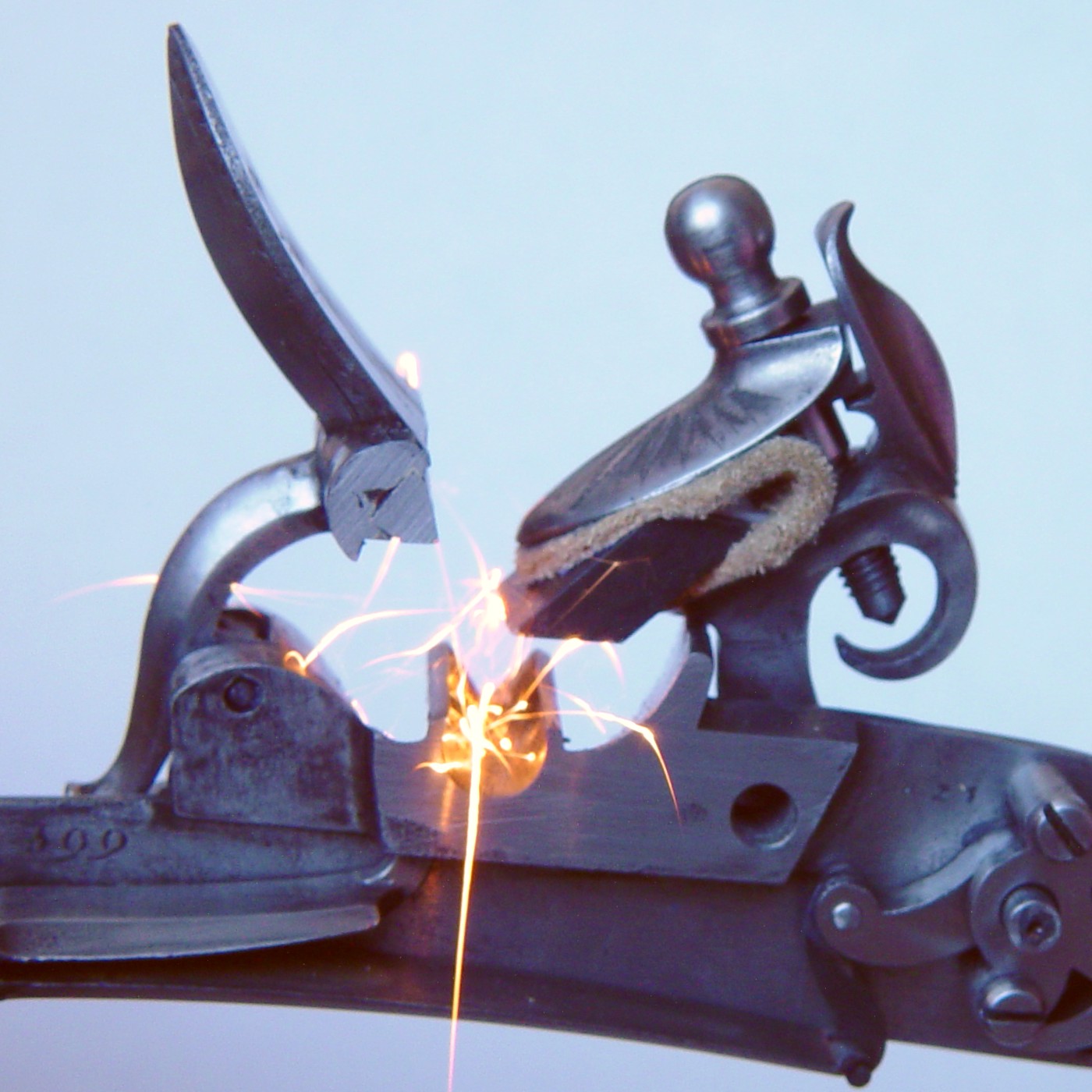
these locks were known as 'flint-eaters' because of their strong springs and good leverage. The first
flint I used was too thin and was good for only one shot, so I switched to a "Dura-Flint", which is
made from cut alumina, similar to cut agate but much tougher. The photo shows how well Manton's lock geometry
works; almost all the sparks shoot directly into the top of the pan. I will shortly be setting up some
experiments to determine actual lock time for this and other locks, so we will see if this lock lives up to its
reputation for speed. All in all, it took about six weeks of off and on work to complete this project. Perhaps 40
hours were spent on the lock and another 40 on this story. If I had to do another one, it would take less than
half that, since a good deal of time was spent staring at the parts deciding what shold be done next.
These locks have a very close geometry and require an
exactly-adjusted flint, inserted bevel-up. The path of the cock-fall makes the flint just graze the frizzen, and
if the flint is just a little too short, the cock cap will strike it instead. As I mentioned in the introduction,
these locks were known as 'flint-eaters' because of their strong springs and good leverage. The first
flint I used was too thin and was good for only one shot, so I switched to a "Dura-Flint", which is
made from cut alumina, similar to cut agate but much tougher. The photo shows how well Manton's lock geometry
works; almost all the sparks shoot directly into the top of the pan. I will shortly be setting up some
experiments to determine actual lock time for this and other locks, so we will see if this lock lives up to its
reputation for speed. All in all, it took about six weeks of off and on work to complete this project. Perhaps 40
hours were spent on the lock and another 40 on this story. If I had to do another one, it would take less than
half that, since a good deal of time was spent staring at the parts deciding what shold be done next.
What's next?
I have two other Manton lock kits on order from TRS, but since there weren't in stock, it may be a while before I receive them... I hope to eventually assemble a Manton fowler and stalking rifle using these and other Manton locks, and I will always be keeping my eyes open for an original. If nothing else, I had a lot of fun building the lock and documenting its progress for all to see.