The Tumbler

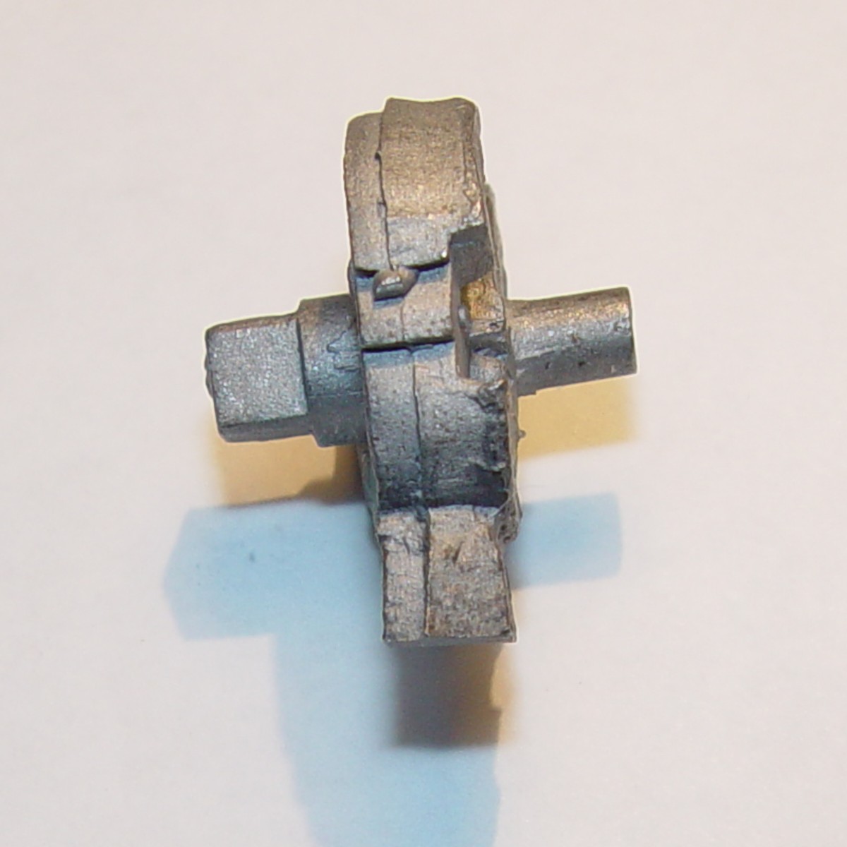 The tumbler casting is extremely rough, so the first step is removing the sprue and any large 'lumps' or
flashing marks left from the mold. Then, if necessary, make sure the tip edge of the tumbler's rear axle is
smooth, flat and free from any lumps or large irregularities, as this will be used as a guide in truing up the
casting. The side of the front tumbler axle also needs to be cleared of any large irregularities.
The tumbler casting is extremely rough, so the first step is removing the sprue and any large 'lumps' or
flashing marks left from the mold. Then, if necessary, make sure the tip edge of the tumbler's rear axle is
smooth, flat and free from any lumps or large irregularities, as this will be used as a guide in truing up the
casting. The side of the front tumbler axle also needs to be cleared of any large irregularities.
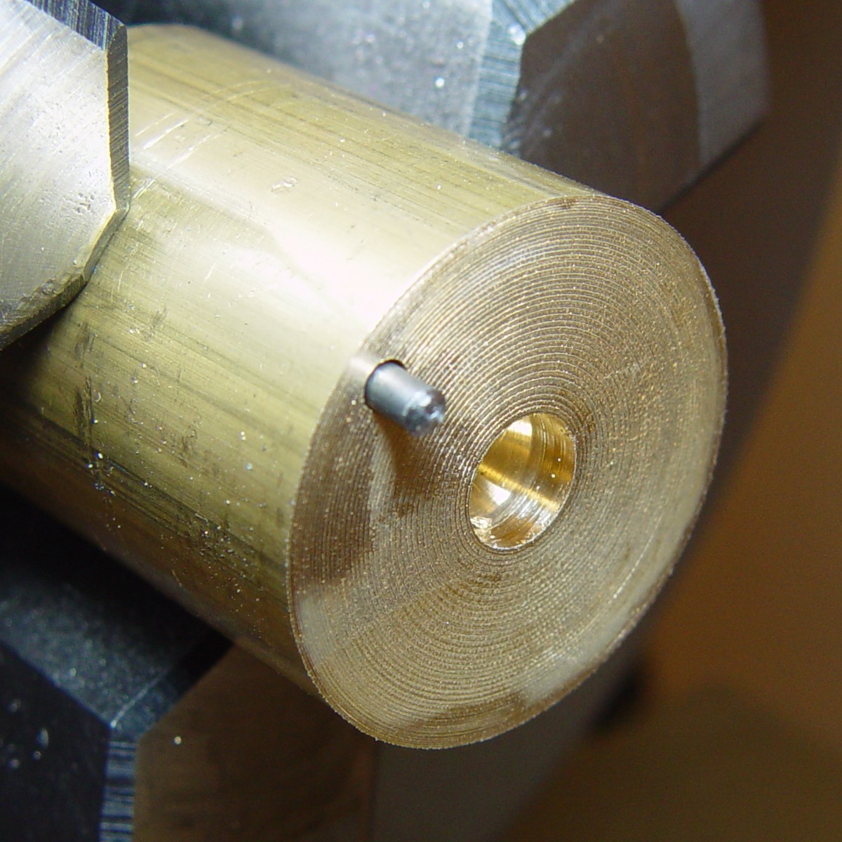 Although it may be possible to grip and turn the tumbler in
a lathe or drill press, when you are dealing with castings this rough, a better technique is needed. A 1"
diameter section of brass rod is placed in the lathe, and a center-drill is used to make a hole. The pilot hole
should be smaller than the rear tumbler axle, but the tip of the axle needs to fit into the conical section
drilled out by the centering drill. The hole should be just deep enough that when the tumbler rear axle is placed
into the hole, the side of the tumbler does not quite touch the brass rod, allowing it to wobble a little bit
when the axle is pressed into the hole. Then, a small hole is placed near the rim of the brass rod, and a pin is
inserted. The tip of the pin must not extend out farther than about midway through the side of the tumbler.
Although it may be possible to grip and turn the tumbler in
a lathe or drill press, when you are dealing with castings this rough, a better technique is needed. A 1"
diameter section of brass rod is placed in the lathe, and a center-drill is used to make a hole. The pilot hole
should be smaller than the rear tumbler axle, but the tip of the axle needs to fit into the conical section
drilled out by the centering drill. The hole should be just deep enough that when the tumbler rear axle is placed
into the hole, the side of the tumbler does not quite touch the brass rod, allowing it to wobble a little bit
when the axle is pressed into the hole. Then, a small hole is placed near the rim of the brass rod, and a pin is
inserted. The tip of the pin must not extend out farther than about midway through the side of the tumbler.
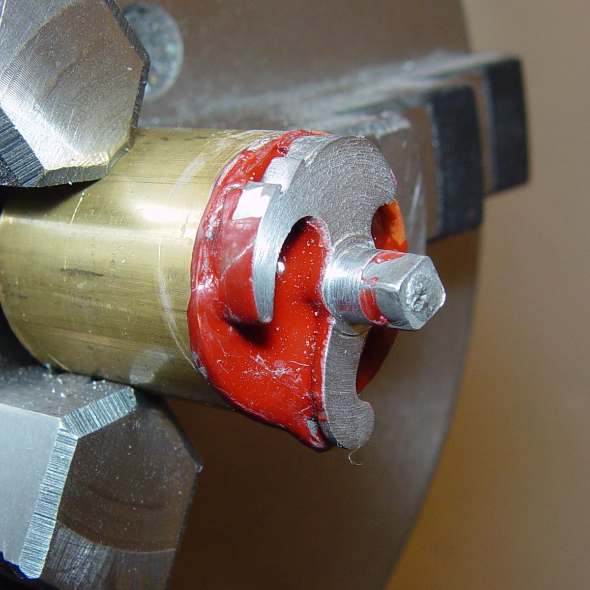
The technique described here is a classical one used by watch and clock makers when they want to precision-turn a part; it is a little harder to explain than to actually do, but with a little practice it can be accomplished in less than a minute. Using a propane torch, heat the side of the brass rod while the lathe is slowly turning, until it is hot enough to 'wipe on' the shellac. Build up about a 1/16" layer by heating both the rod and the stick of shellac (it doesn't have to be uniform), then press the tumbler onto the surface. Keep some pressure on it by mounting a small dowel in the tailstock and pressing the end of the dowel into the front of the axle; the dowel should be free to wobble as much as it wants (you can also hold the dowel by hand, but one tends to run out of hands in a hurry...). Warm both the bar and the tumbler and add more shellac to cover the pieces as shown. Then, while the pieces continue to turn in the lathe at 300 RPM or so (just slow enough so the shellac doesn't fly off), put pressure on the side of the front axle to true it up. As the shellac sets, the wobble should diminish, and when cool, it should run completely true. Another method is to mount a smooth tool in the lathe tool holder and slowly advance it, bearing on the side of the axle, until the wobble JUST stops. However, if you go too far, the piece will break off when it cools - that's why I generally prefer to use just hand pressure. It may take a few tries to get the hang of it, but this technique will guarantee the front axle is exactly centered with the rear axle.
 Next, using a very sharp cutting bit, carefully turn the
axle. The cast axle is not completely round, but if looks like it requires removal of more than 0.003" of
material from one side, the piece should be warmed and re-trued. Take slow, careful cuts, advancing the tool no
more than 0.002" at a time until the axle is about 0.252" in diameter; the final diameter is to be
0.250", but the remainder of material will be removed after hardening and tempering.
Next, using a very sharp cutting bit, carefully turn the
axle. The cast axle is not completely round, but if looks like it requires removal of more than 0.003" of
material from one side, the piece should be warmed and re-trued. Take slow, careful cuts, advancing the tool no
more than 0.002" at a time until the axle is about 0.252" in diameter; the final diameter is to be
0.250", but the remainder of material will be removed after hardening and tempering.
 Next, back the tool all the way out and begin cutting the
sides of the tumbler. Stop when you get to within 0.030" of the axle. Continue removing material at no more
than 0.005" at a pass until the entire casting face is clean. Then move out 0.010" and cut the rest of
the way to the axle. This leaves a small ring around the axle as a bearing surface, which will prevent the rest
of the tumbler from scraping the lockplate. Locks with this feature were common in the late flint period and are
referred to as 'ghosted', since there is a whisp of light to be seen between the tumbler and the plate.
Finally, drill and tap the front axle for a 6-32 screw.
Next, back the tool all the way out and begin cutting the
sides of the tumbler. Stop when you get to within 0.030" of the axle. Continue removing material at no more
than 0.005" at a pass until the entire casting face is clean. Then move out 0.010" and cut the rest of
the way to the axle. This leaves a small ring around the axle as a bearing surface, which will prevent the rest
of the tumbler from scraping the lockplate. Locks with this feature were common in the late flint period and are
referred to as 'ghosted', since there is a whisp of light to be seen between the tumbler and the plate.
Finally, drill and tap the front axle for a 6-32 screw.
Remove the brass rod from the lathe, warm it and remove the tumbler. Reverse the rod in the lathe, flatten its face and cut a hole wide enough to clear the raised bearing surface and deep enough to accommodate the front axle. The sides of the tumbler should be able to lie perfectly flat on the surface of the rod. As before, fix the tumbler to the rod with shellac and true it up. Note that the reference point for the first truing was the end of the rear axle; this time it is the turned-flat face of the tumbler, so the tumbler must be held tight and flat to the face of the rod as it is trued. Turn the rear axle until it is just round, and turn flat the tumbler face as before, leaving the 0.030" wide bearing surface.
 The axle hole for the tumbler fly shows up as a tiny bump
(perhaps the bump was the axle itself?) cast in place, and if it was an axle, it would be almost impossible to
finish. Instead, I drilled out the old axle nub and made a blind 0.055" hole for a new axle and used a tiny
end mill to provide clearance around the axle hole. The tumbler is then removed and cleaned. The sides can be
honed to remove some of the roughness left by the turning, and the sear and periphery of the tumbler smoothed.
The half-cock notch can be cleaned out with a slotting file or an abrasive disk (I prefer a diamond disk) in a
Dremel-type tool. Flatten the sides of the square post and then harden and temper it to a just-blue color.
The axle hole for the tumbler fly shows up as a tiny bump
(perhaps the bump was the axle itself?) cast in place, and if it was an axle, it would be almost impossible to
finish. Instead, I drilled out the old axle nub and made a blind 0.055" hole for a new axle and used a tiny
end mill to provide clearance around the axle hole. The tumbler is then removed and cleaned. The sides can be
honed to remove some of the roughness left by the turning, and the sear and periphery of the tumbler smoothed.
The half-cock notch can be cleaned out with a slotting file or an abrasive disk (I prefer a diamond disk) in a
Dremel-type tool. Flatten the sides of the square post and then harden and temper it to a just-blue color.
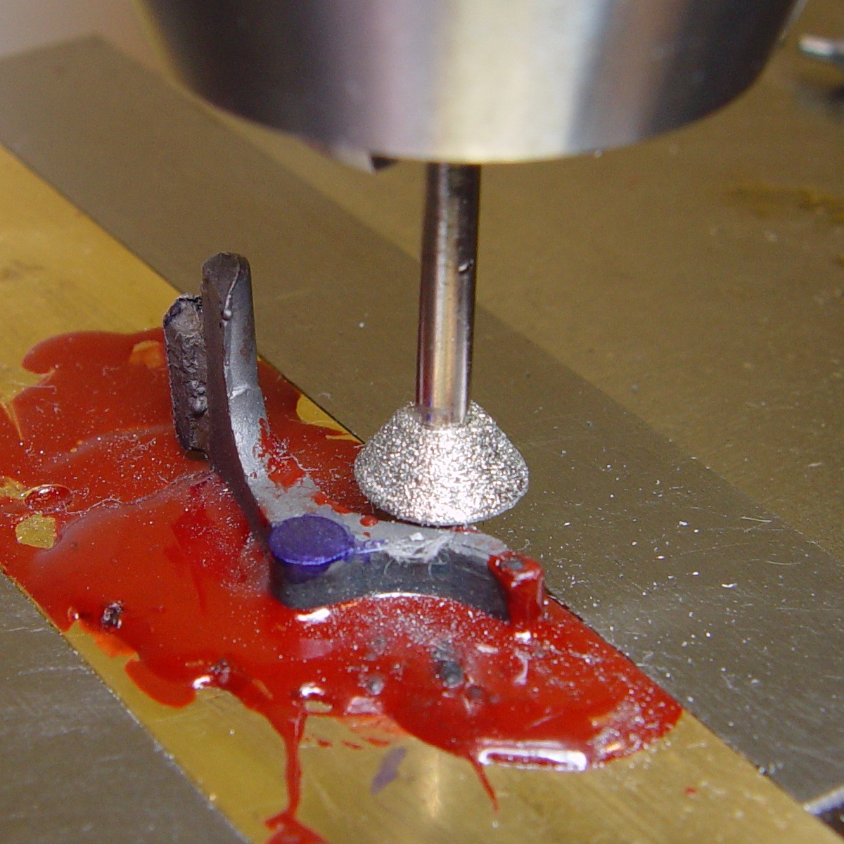
The fly flew...
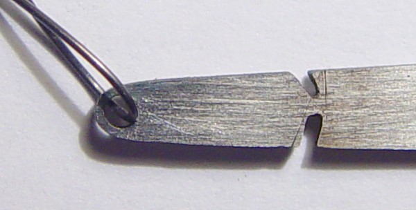 The kit of lock parts listed the fly, but I could find no trace of it in the parts bag. I
debated whether to bother with a fly, since I will probably use this lock on a fowler or stalking rifle, but I
decided to make one for two reasons. First, it would make the lock 'complete', and second, it would
protect the sear. The Manton V-pan lock is rather delicate, and the sear is a long, thin blade of hard metal
which might chip or shatter if the cock was accidentally released and the sear dropped onto the half-cock notch.
Having a fly would prevent this (although the gun might go off...). I found an old piece of a flat needle file
and ground it down to 0.035" for the body of the fly. A 0.055" hole was drilled for the axle, and the
fly was cut to size. Note the wire through the hole during the parting operation; I didn't do this on my
first attempt, and the fly truly flew (and vanished). The wire prevents embarrassing accidents like that.
The kit of lock parts listed the fly, but I could find no trace of it in the parts bag. I
debated whether to bother with a fly, since I will probably use this lock on a fowler or stalking rifle, but I
decided to make one for two reasons. First, it would make the lock 'complete', and second, it would
protect the sear. The Manton V-pan lock is rather delicate, and the sear is a long, thin blade of hard metal
which might chip or shatter if the cock was accidentally released and the sear dropped onto the half-cock notch.
Having a fly would prevent this (although the gun might go off...). I found an old piece of a flat needle file
and ground it down to 0.035" for the body of the fly. A 0.055" hole was drilled for the axle, and the
fly was cut to size. Note the wire through the hole during the parting operation; I didn't do this on my
first attempt, and the fly truly flew (and vanished). The wire prevents embarrassing accidents like that.
The Bridle
 First, measure the thickness of the tumbler at the bearing
collar; I found mine to be 0.210". Since we need a little clearance, the height of the bridle off the
lockplate should be about 0.216". Begin by filing and flattening both sides of the bridle. Check the
thickness along the bridle plate and file it if necessary to make the sides parallel. Mount the plate as shown,
making sure it is perfectly flat on the bar and that the bar is held flat. Gently grind the posts until they are
the correct length, then and drill these and the trigger sear hole through to take a 4-40 screw (#34 drill,
followed by a #32). Keep in mind that if there is not already a hole behind the post where the drill will exit,
the bridle will pop off of the bar because it is pushed by the dimple of metal formed as the drill exits. I
simply accept this and re-melt the shellac.
First, measure the thickness of the tumbler at the bearing
collar; I found mine to be 0.210". Since we need a little clearance, the height of the bridle off the
lockplate should be about 0.216". Begin by filing and flattening both sides of the bridle. Check the
thickness along the bridle plate and file it if necessary to make the sides parallel. Mount the plate as shown,
making sure it is perfectly flat on the bar and that the bar is held flat. Gently grind the posts until they are
the correct length, then and drill these and the trigger sear hole through to take a 4-40 screw (#34 drill,
followed by a #32). Keep in mind that if there is not already a hole behind the post where the drill will exit,
the bridle will pop off of the bar because it is pushed by the dimple of metal formed as the drill exits. I
simply accept this and re-melt the shellac.
On the inside of the lockplate, find the small pit which represents the top bridle hole, drill and tap it for 4-40. Mount the bridle using the one screw and look through the lower bridle screw hole and center it on the lower pit as well as possible. Also look through the sear screw hole and make sure it lines up fairly well with its pit. Firmly tighten the top screw and mount the lockplate for drilling. Use the #32 drill as a centering drill, going through the existing hole in the bridle, and then drill with a #42 for another 4-40 thread. Install and tighten the lower bridle screw and similarly, center through the trigger sear hole and drill and tap the lockplate for the sear screw.
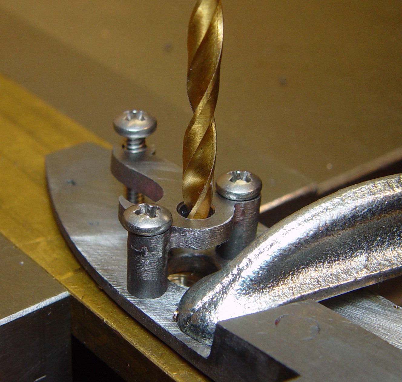 Remove the bridle and lightly file the back of the
lockplate to remove any burrs. Mount the lockplate absolutely flat and drill a 0.250" hole where the axle
pit is found (start with 15/64", finish with 1/4"). Then, without moving the assembly, install and
tighten the bridle. In this picture, I have temporarily used some regular machine screws; proper ones will be
made later. Use a centering drill to make a pit in the bridle top and then drill to a size just under the
diameter of the rear tumbler axle. Remove the bridle and chamfer the inside of the tumbler axle holes on both the
lockplate and bridle.
Remove the bridle and lightly file the back of the
lockplate to remove any burrs. Mount the lockplate absolutely flat and drill a 0.250" hole where the axle
pit is found (start with 15/64", finish with 1/4"). Then, without moving the assembly, install and
tighten the bridle. In this picture, I have temporarily used some regular machine screws; proper ones will be
made later. Use a centering drill to make a pit in the bridle top and then drill to a size just under the
diameter of the rear tumbler axle. Remove the bridle and chamfer the inside of the tumbler axle holes on both the
lockplate and bridle.
Wrap some #220 wet emery paper around a screw and spin it in the lockplate's tumbler axle hole to polish the inside. Mount the rear axle of the tumbler in a drill chuck and polish the side of the front axle with a diamond hone or wet emery paper. Test for a fit in the lockplate and hone until it just fits. Repeat this process with the rear tumbler axle and bridle. Then assemble the lockplate, tumbler and bridle to see if it all works smoothly. If it binds, do what is necesary to get it just moving. When it looks OK, finish, polish and harden the bridle, then temper it to a blue-purple.
Second error - the sear axle hole...
The usual arrangement for the sear axles is to treat them like the other bridle screws (which I did), with the axle screwing through the bridle into the lockplate. In looking at actual old Manton V-pan locks, it seems he had a different system. The sear axle was screwed into the lockplate from the front, with the axle going through an unthreaded hole in the bridle. If you think about it, this is a better arrangement. In the common way of doing this, if the sear axle screw is over-tightened, it can bind the sear by putting pressure on the bridle, and if it is too loose, it can work out. With the Manton system, the axle can be fully tightened without distorting the bridle. I 'fixed' the problem by drilling out the lockplate for a 6-32 screw and made the axle accordingly. The only consequence of the repair was the axle (for the hole originally drilled at 0.116") was slightly oversized from what it would have been (0.101"), and thus was 'candy striped' by the threads.
The Trigger Sear and Cock
 The sear is also 'ghosted' about 0.010" by bosses
on the axle hole, so the lockplate side of the sear was filed flat around the boss. A hole was drilled in a brass
bar so the boss would be sitting in it, allowing the sear to be stuck flat to a bar, the proper alignment for
hole drilling. The top of the boss was ground flat, and the sides were cleared of flashing and smoothed. The boss
was then drilled for the sear axle. The sear geometry was roughed in, and then the sear was hardened. In
tempering the sear, the sear itself was held gently in a pair of pliers to keep its temperature down, and the
body of the sear was tempered to a deep blue. The heat-sinking of the pliers kept the sear tip to a deep straw
temper. Final sear shaping was done with a diamond hone.
The sear is also 'ghosted' about 0.010" by bosses
on the axle hole, so the lockplate side of the sear was filed flat around the boss. A hole was drilled in a brass
bar so the boss would be sitting in it, allowing the sear to be stuck flat to a bar, the proper alignment for
hole drilling. The top of the boss was ground flat, and the sides were cleared of flashing and smoothed. The boss
was then drilled for the sear axle. The sear geometry was roughed in, and then the sear was hardened. In
tempering the sear, the sear itself was held gently in a pair of pliers to keep its temperature down, and the
body of the sear was tempered to a deep blue. The heat-sinking of the pliers kept the sear tip to a deep straw
temper. Final sear shaping was done with a diamond hone.
The pit in the lockplate for the sear spring pin was chased out with a graver. The sear spring was drilled for a 4-40 screw using the same technique used for the frizzen spring; use caution, the walls are thin, so center the drill very carefully. The spring casting was a little thick, so the free leaf was thinned a little bit during the clean-up of the casting and finally when it was finished and in place. Keep in mind - the stiffness of a spring is in proportion to the cube of its thickness (cutting thickness by 1/2 cuts stiffness to 1/8), so make careful adjustments and test frequently.
The two critical cock operations are opening the square hole for the tumbler and drilling the cock cap screw hole. The tumbler axle end should have been smoothed previously, and the sides should have a slight taper. Using a square file, the hole in the cock is slowly opened up until the proper fit is achieved. This must be done slowly and carefully, checking not only how well the parts fit but also making sure the cock remains square with the axle. I find it helps to over-taper the cock hole in the early part of the fitting, and when the axle will just fit the hole, I place the cock on a brass block, insert the tumbler and then gently tap the tumbler rear axle with a copper hammer. Since the tumbler is relatively hard compared to the annealed cock, this turns up little ridges in the hole where the fit is too tight. Machinist's blue can also be painted on to see where metal must be removed. Just remember the final fit must be tight; if you overfile the hole, the sides can be closed slightly by using a punch around its edges.
To drill the hole for the cock cap screw, first clean out the cock cap screw hole and remove the sprue at the rear; I found the cleaned hole to be slightly larger than a 10-32 screw size, with extra front-back play. Since the cock in this lock is straight, it can be mounted by clamping the axle-hole area between two brass blocks in the drilling vise. Make sure it is indeed vertical, and then center the drill in the sideways direction so it bisects the top of the cock. Mount a reversed drill which just fits the cock cap hole in the chuck and as the drill is turning slowly, move the assembly backwards until the drill contacts the cock post. Adjust the back-forth angle of the cock until the drill lies completely flat against the front surface of the post. Next, back the drill a little and put the drill shaft through the cock cap hole, and then move the drill again until the back of the cock cap contacts the cock post, leaving no play when the cock cap is flat against the post. Remove the reversed drill and drill the hole for threading a 10-32 screw.
